
Cut two foam mats in half, and their cores may look quite different. One may show closely spaced cells with a fairly even distribution. The other may contain coarse pockets, stretched cells, thin walls, or a noticeable change between the surface and the center. Those differences are useful clues, but a cross-section is not a pass/fail test on its own.
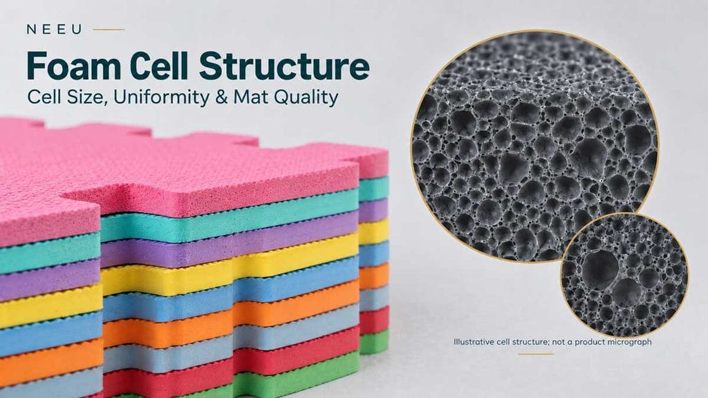
For a mat buyer, the practical question is not whether the foam has the smallest possible cells. It is whether the cellular structure is consistent with the approved sample and supports the required cushioning, recovery, dimensions, surface, and service conditions.
This guide explains what buyers can learn from a foam cross-section, what a photograph cannot prove, and how to turn a visual observation into a repeatable sample or production check.
What a Foam Cross-Section Can Tell You
A polymer foam contains a solid polymer phase and a gas-filled cellular phase. A section through the material exposes the geometry created as cells nucleated, expanded, and became fixed during processing.
The section can help a buyer identify:
- whether most cells appear similar in size or vary widely;
- whether isolated oversized cells or voids are present;
- whether cells are rounded, stretched or strongly oriented;
- whether cell walls look intact, torn, merged or collapsed;
- whether the core changes from the skin to the center;
- whether laminated layers are aligned and bonded consistently; and
- whether production samples resemble the approved reference.
It cannot, on its own, establish density, hardness, compression recovery, water absorption, chemical compliance, or service life. A microscope image also does not automatically prove that a foam is closed-cell. Cutting through a closed cell opens it at the observation plane, while a two-dimensional image cannot show every connection within the three-dimensional structure. For the broader structural distinction, see the guide to closed-cell foam.
The Five Features Buyers Should Read in a Foam Section
1. Cell size
Cell size describes the dimensions of the visible cavities. Researchers may report a diameter or an equivalent diameter calculated from cell area. Commercial inspection may use a calibrated optical microscope, while research often uses scanning electron microscopy (SEM).
An average can be useful when the sampling and calculation method are fixed. It is still only one summary value. Two foams can share the same average, yet one has a narrow distribution while the other combines many small cells with a few large voids.
This is why a drawing or purchase specification should not state only “fine cells” or a bare average. If cell size is important to the product, define the imaging method, locations, orientation, magnification, and how the distribution will be reported.
2. Cell-size distribution
Uniformity refers to the spread and spatial consistency of the cell population, not to every cell being identical. Real commercial foam contains variation.
A narrow, stable distribution can support more even local behavior, but the acceptable distribution depends on the material, density, expansion ratio, thickness, and intended use. A bimodal structure may also be deliberately engineered in some foam systems. The useful buyer question is whether the observed distribution is intentional, controlled, and repeatable.
Look beyond the center of a carefully selected image. Compare several fields from the center, edges, and different production positions. Record rare but important defects such as large cavities even if they have little effect on the calculated mean.
3. Cell shape and orientation
Cells may appear round, polygonal, or elongated. Elongation can result from material flow, expansion direction, compression during forming, or subsequent mechanical strain. It can also appear simply because the sample was cut in a different direction.
For that reason, images from different suppliers are not comparable unless the cutting plane is identified. If direction matters, such as along and across an extruded sheet, examine both orientations. Aspect ratio or circularity can be recorded when a project needs more than a visual description.
4. Cell walls, windows and coalescence
The polymer between cells carries load and helps the foam hold its shape. A section may reveal:
- unusually thin or torn walls;
- holes or windows connecting adjacent cells;
- merged cells that form a larger cavity;
- collapsed zones where the structure did not remain stable; or
- a local solid region where expansion was restricted.
These observations can explain why a buyer should investigate a weak edge, uneven feel, or persistent indentation. They do not identify the cause by themselves. Similar-looking defects can result from different combinations of formulation, dispersion, temperature, pressure, crosslinking, gas generation and cooling.
5. Skin-to-core and layer variation
The outside of a molded or extruded foam may cool and constrain expansion differently from the center. A denser skin, a gradual change in size, or cells oriented near a surface can therefore be part of the process rather than a defect.
The issue is whether that profile is appropriate for the finished mat and remains consistent. In a laminated product, inspect the foam on both sides of the bond line and at the interface. Delamination, trapped voids, or a locally compressed core can affect the finished construction even when the base foam looks acceptable elsewhere.
Is a Smaller Cell Size Always Better?
No. Smaller cells are often associated with improved mechanical behavior in controlled polymer-foam studies, but cell size rarely changes in isolation.
A 2022 review by Pang and colleagues describes cell size, cell density, and expansion ratio as three linked descriptors of polymer microcellular foam structure.[1] A 2024 review of microcellular and nanocellular foams makes the experimental limitation especially clear: it is difficult to produce specimens with the same foam density but different cell sizes, making it hard to isolate the independent effect of size.[2]
The NEEU literature library shows the same interaction in EVA-containing systems:
- In a supercritical-nitrogen study of EVA/POE/TPU blends, changing TPU content refined the cells and narrowed their size distribution under the tested conditions. Density, hardness, and mechanical properties changed simultaneously.[3]
- In radiation-crosslinked EVA/POE/EPDM foam, insufficient network development was associated with poor cell retention, while a more restrictive network could limit expansion. The useful lesson is that the polymer must gain enough strength at the right stage; the reported formulation is not a universal EVA mat recipe.[4]
- In molded EVA/EPDM/OBC foam, excessive OBC in the tested blend was associated with larger cells, thinner walls, and more rupture or coalescence. Compression-set behavior also changed.[5]
- An EVA/PEBAX study measured five SEM fields per sample and reported both average diameter and cell density. It also found that a formulation change could create more nucleation sites yet still lead to broader cell sizes and coalescence when compatibility and melt strength were unfavorable.[^66]
Together, these studies support a limited but useful conclusion: cell morphology should be evaluated alongside density, expansion, formulation, and finished-product performance. They do not establish a single ideal cell diameter for every EVA, XPE, TPE, or PVC mat.
How Cell Structure Develops During Foaming
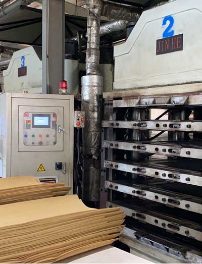
Cell formation can be described as a sequence, although several events overlap in real production.
Gas becomes available. It may be generated by a chemical reaction or decomposition, dissolved into a polymer as a physical blowing gas, or introduced through another method suited to the material. The article on foam blowing agents explains why the identity of the agent alone does not predict the final structure.
Cells nucleate. Small gas regions begin to form. Interfaces, particles, crystallinity, dissolved-gas conditions, and the local state of the polymer can change the number and location of nucleation sites.
Cells grow. Gas diffuses into the cells and internal pressure drives expansion. The polymer must deform without allowing uncontrolled gas loss.
The structure stabilizes. Cooling, crystallization, curing, or crosslinking helps the foam retain its expanded geometry. If gas generation, polymer strength, and the forming window do not align, cells may merge, rupture, shrink, or remain under-expanded.
Mechanical, physical, and chemical routes supply and manage gas differently. They should be compared as production systems rather than ranked by name. See mechanical, physical and chemical foaming methods for that distinction.
What Causes Uneven or Damaged Cells?
An abnormal section is a starting point for investigation. Common process categories include:
Poor dispersion. Local concentrations of a blowing agent, crosslinking ingredient, filler, pigment, or other additive can create uneven nucleation and expansion.
Gas-release timing that does not match material strength. If gas becomes available before the polymer can retain it, cells may merge or escape. If the structure becomes too restrictive too early, expansion may be limited.
Uneven heat or pressure history. Temperature gradients, inconsistent residence time, mold filling, or pressure release can produce skin-to-core or position-to-position variation.
An unsuitable viscosity or crosslinking window. A material that is too fluid may not support growing cells; one that is too restrictive may resist expansion. The required window depends on the polymer and forming route.
Cooling, shrinkage, or conditioning effects. A foam can continue changing after expansion. Compare samples only after an agreed conditioning period.
Cutting damage. A blunt blade can drag, compress, or smear flexible foam. A brittle-fractured research sample and a blade-cut production sample may exhibit different surface appearances even when taken from the same material.
NEEU’s foam mat foaming process page places these factors within the wider manufacturing stage. A root-cause review should then use the actual batch records and finished-mat results; a generic cell photograph cannot identify a formulation error.
How to Inspect a Foam Cross-Section
State what prompted the inspection. Examples include an uneven feel, an oversized cavity, an edge failure, a recovery complaint or routine sample approval. This determines where to cut and which performance test to run next.
Take samples from named locations
For a mat or sheet, define the center, edge, and any position related to the suspected defect. For a laminated or textured mat, retain the complete thickness. Compare equivalent positions across samples and production lots.
Keep the cutting direction consistent
Record whether the image is through the thickness, along the machine direction or across it. Use a fresh, appropriate cutting tool and avoid squeezing the specimen during preparation. If deformation from cutting is likely, document the preparation method or use a laboratory technique suitable for the material.
Use calibrated images
Every measurement image should include a scale bar or a traceable calibration. Keep lighting, magnification and image processing consistent. A photograph without scale can show a severe void, but it cannot support a cell-size comparison.
Measure more than one field
Choose several fields using a predefined pattern instead of selecting only the most uniform area. Record the number of cells measured and the locations. For heterogeneous foam, show the distribution or range as well as the average.
Compare morphology with performance
If the concern is a dent, measure compression recovery or compression set. If it is edge breakage, assess the relevant strength or assembly behavior. If the cushioning is uneven, compare thickness, density, and indentation response at the named positions. The image helps direct the investigation; the performance test answers the buyer’s use question.
A Practical Cross-Section Comparison Record
| Record item | What to document | Why it matters |
|---|---|---|
| Product identity | Material, construction, thickness, sample or lot code | Prevents images from being detached from the actual product |
| Sample location | Center, edge, corner, roll position or molded position | Reveals local and position-related variation |
| Cutting plane | Through-thickness, machine direction or transverse direction | Prevents orientation from being mistaken for a process difference |
| Preparation | Blade cut, cryogenic fracture or laboratory method | Identifies possible preparation artifacts |
| Image settings | Magnification, scale bar, lighting and instrument | Makes repeat comparison possible |
| Cell statistics | Measurement rule, number of cells, average and distribution or range | Avoids relying on one selected field or one mean value |
| Visible anomalies | Large voids, torn walls, coalescence, collapse, dense zones or delamination | Preserves defects that averages may hide |
| Companion results | Density, thickness, hardness, and the performance test related to the complaint | Connects morphology to the buyer’s real requirement |
Research methods can provide useful ideas, but a buyer should confirm that a proposed standard applies to the actual material. ASTM D3576, for example, covers apparent cell size in rigid cellular plastics and warns that more detailed analysis may be required when average size or distribution varies across a specimen.[7] ISO 4590 addresses open- and closed-cell volume in rigid cellular plastics.[^88] Neither title should be copied into a flexible EVA mat specification without checking scope and method suitability.
Turning an Image Into a Purchase Requirement
Terms such as “dense cells,” “fine foam” and “uniform structure” are open to interpretation. A useful RFQ or purchase specification should say how the requirement will be judged.
Include the following where cell structure is relevant:
- the finished material and complete construction to be supplied;
- the approved reference sample or signed cross-section image;
- named sample locations and cutting orientation;
- the agreed imaging and measurement method;
- how many fields and cells will be evaluated;
- the statistic to report, including distribution or range where needed;
- defined visual reject conditions, such as oversized voids or collapsed zones;
- the companion physical tests and their conditioning; and
- the action required when the result falls outside the approved window.
Do not set a numerical cell-size limit simply because it appears in a paper or another supplier’s data sheet. Start with representative EVA foam mat samples, determine which structure best supports the application, and then preserve that result using a measurement method that both the supplier and buyer can repeat.
Questions Buyers Commonly Ask
Not automatically. Smaller cells may support certain properties in a controlled formulation, but density, expansion ratio, polymer type, cell walls, crosslinking,, and surface structure also affect the results. Quality means consistently meeting the finished mat requirement.
It has a controlled distribution across the areas that matter, without unexplained large voids, collapsed zones, or abrupt local changes. Uniform does not mean that every cell is the same size.
A phone photo can document obvious defects and production differences. Quantitative comparison requires a consistent cut, orientation, magnification, and scale. A microscope or calibrated imaging setup is more suitable for cell measurements.
No. Cell density usually refers to the number of cells per unit volume, calculated using a defined method. Foam density is mass per unit volume. Use the full term and unit so the two are not confused.
It can show morphology consistent with a closed-cell structure, but a two-dimensional cut does not quantify three-dimensional cell connectivity. Use an applicable method when open- or closed-cell content must be measured.
The surface and core can experience different temperature, pressure, cooling, and expansion histories. The pattern may be process-related, but its acceptability depends on the product specification and consistency across samples.
Use the finished construction whenever the commercial question concerns the finished mat. A foam block can support process development, but cutting, compression, texture, and lamination can change what the buyer receives.
Compare the Structure That the Finished Mat Actually Uses
A clear section image is valuable when it is tied to the product, location, preparation method, and a relevant physical test. Without that context, it is easy to reward a neat-looking picture that says little about how the mat will perform.
For a sample review, send NEEU the target application, material, thickness, density, and performance concern. We can use that brief to discuss which cross-section views and finished-mat checks should be included before mass production.
- Pang, Y., Cao, Y., Zheng, W., and Park, C. B. (2022). “A comprehensive review of cell structure variation and general rules for polymer microcellular foams.” Chemical Engineering Journal, 430, 132662. https://doi.org/10.1016/j.cej.2021.132662. General microcellular-foam review; not a finished-mat specification. ↩︎
- Le Barbenchon, L., and Kopp, J.-B. (2024). “A review on the mechanical behavior of microcellular and nanocellular polymeric foams: What is the effect of the cell size reduction?” Journal of Cellular Plastics, 60(5-6). https://doi.org/10.1177/0021955X241246066. Used because cell size is difficult to isolate from foam density. ↩︎
- Zhang, D., Wang, T., and Liu, Y. (2026). “Effect of TPU on the cell structure and properties of EVA/POE/TPU foamed materials” [translated title]. China Elastomerics, 36(3), 37-43. https://doi.org/10.16665/j.cnki.issn1005-3174.2026.03.004. Supercritical-N2 EVA/POE/TPU formulation study; not a universal EVA mat comparison. ↩︎
- Xu, J., Zhao, W., Huang, C., et al. (2020). “Preparation and Properties of Radiation Cross-Linked EVA/POE/EPDM Foaming Material.” Plastics, 49(6), 21-24. Radiation-crosslinked blend followed by chemical foaming; findings are limited to the tested blend and process. ↩︎
- Xing, E., Su, Q., Zou, C., et al. (2025). “Crystallization behavior of EVA/EPDM/OBC blends and structure and properties of their foamed materials.” China Synthetic Resin and Plastics, 42(2), 66-71. https://doi.org/10.19825/j.issn.1002-1396.2025.02.15. Molded EVA/EPDM/OBC study; reported formulation values are not transferred to commercial mats. ↩︎
- Huang, G., Gui, Y., Li, Y., et al. (2021). “Preparation and Characterization of EVA/Nylon Elastomer Microcellular Foaming Materials.” China Plastics, 35(9), 1-7. https://doi.org/10.19491/j.issn.1001-9278.2021.09.001. Chemically foamed EVA/PEBAX formulation study; used for measurement design and interaction among nucleation, compatibility and cell growth. ↩︎
- ASTM International. ASTM D3576-25, Standard Test Method for Cell Size of Rigid Cellular Plastics. Official ASTM standard page. Scope checked on the official page; applicability to flexible mat foam must be confirmed before use. ↩︎
- International Organization for Standardization. ISO 4590:2016, Rigid cellular plastics – Determination of the volume percentage of open cells and of closed cells. Official ISO standard page. Scope checked on the official page; not presented here as a flexible EVA mat method. ↩︎